LABORATORY EXPERIMENT #4
RELIABILITY EXPERIMENT -- DESIGN AND TESTING OF A
SINGLE-ERROR-CORRECTING CHANNEL
Copyright 2000, Alan V. Sahakian
GOAL:
To learn about the use of parity in detecting and correcting errors. To design, construct, debug and demonstrate a single-error-correcting data channel based on the Hamming code. To predict the reliability of such a channel.
LAB DESCRIPTION:
In this lab you will design and build a four-bit Hamming-code-based single-error-correcting circuit. Such a circuit could be used, for example, to make a single-error-correcting memory system which can work correctly even if one bit-plane is defective or has corrupted data.
BACKGROUND:
Parity is a simple concept. Given an n-bit binary value, the parity is of that value is 1 if and only if the number of bits in that value which are set to 1 is odd. Parity forms the basis of a number of error-detection and error-correction schemes. For example, in serial data transmission each n-bit group (e.g. an 8-bit byte) of data bits may be appended with a bit reflecting the parity of the group. Upon receipt of this group of N bits and the appended parity bit, the parity is re-calculated and compared with the value of the received parity bit. If these are different then at least one bit is known to have been altered in transmission (including, possibly, the parity bit itself).
A common way of describing this is that the appended bit forces the parity of each and every (N+1)-bit group to be even or to be odd (depending on the convention in use). A single-bit change to any group will change its parity and make the error detectable. Note that any odd number of bit changes (including a single-bit change) will alter the parity, but any even number of bit changes will not.
The parity of the N-bit value X may be expressed as:
Mod2[x0 + x1 + ... + xn + ... + xn-1]
where xn is the n'th bit of X.
This result is easily generated using exclusive-or gates, since the operation of summing and then taking the least-significant bit (which is the Mod2 operation) is the same as simply exclusive-or'ing (XOR'ing) all N bits together.
Note that a parity bit may be thought of as a "check" bit, since it checks the integrity of the bits which it was calculated on. Errors (alterations) in data may occur due to electronic noise, charges induced by particles from nuclear decay (such as alpha particles from the decay of carbon 14 in the packaging material of ICs, although most memory ICs now have coatings to reduce this effect), the permanent failure of an IC (for example, due to the failure of a wire bond), or some other physical event. If an error is transient (does not happen consistently) it is called a soft error; if it is permanent it is called a hard error.
ERROR-CORRECTING CODES:
Imagine an N-bit value which is partially checked by a number of different parity (check) bits such that any single-bit alteration in that value will give a unique change in the check bits. It would thus be possible to determine if any single bit in the value has been altered, and if so, which bit. This knowledge is enough to correct the value in the case of any single-bit alteration (error). R.W. Hamming [1950] was the first to detail practical codes based on this idea. Since that time his work has been extended to yield codes which can detect and correct multiple-bit errors. A generally-used notation to describe such codes is as X-Error-Detecting Y-Error-Correcting. For example the Hamming code is a Single-Error-Detecting Single-Error- Correcting (SED SEC) code. A single appended parity bit yields a SED code. Often a code which can correct a Y-bit error will be able to detect, but not correct an error of more than Y bits.
THE HAMMING CODE:
Hamming's code is simple and elegant. M check bits are interleaved with N data bits yielding an M+N-bit value. The required number of check bits, M, can be calculated as the smallest integer satisfying:
M >= log2(M + N)
The bits are subscripted starting with X1. Each bit with a subscript which is an exact power of two is a check bit and each other bit is a data bit. Each check bit checks a unique combination of data bit as follows. Consider that each subscript is written-out as a binary value (e.g. 4 is written as 0100, 5 is written as 0101, etc.). Each check bit is calculated as the parity (XOR) of those bits having a "1" in its subscript in the same position as that check bit.
The resulting M+N-bit value has the property that any single-bit change may be exactly identified and therefore reversed (corrected). Assume that the value was stored in a faulty memory and when retrieved, one bit is now in error. If the M check bits are recalculated from the retrieved N data bits and compared (using XOR operations) with the retrieved M check bits, the result will be the subscript of the bit which is in error and this bit can be inverted to correct the data. The result of this comparison is called the Syndrome. If there was no error (either because there was no fault, or because the data stored and retrieved was not affected by the fault) then the syndrome will be all 0's. If a check bit itself is in error, the syndrome will point to that check bit but, in general, no corrective action will be taken. In general, any errors which occur must be logged somehow so that the fault can be repaired.
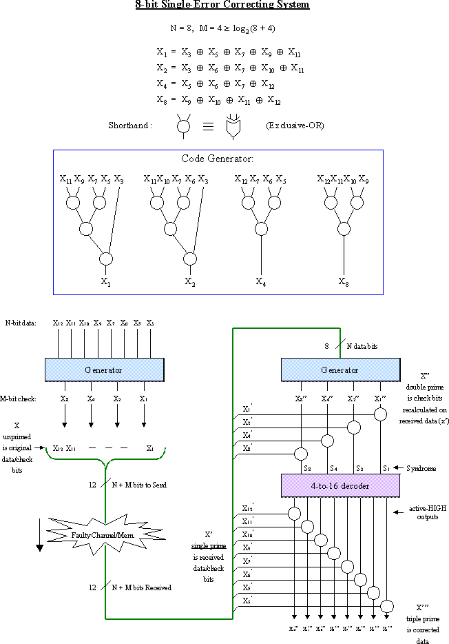
To help you understand the Hamming-code SEC system, I have designed an N=8 (M=4) example for you. This is included at the end of this lab description.
RELIABILITY OF AN SEC MEMORY SYSTEM:
In lecture we have studied models of reliability of electronic components (the exponential model). We know that if a system consisting of many subsystems (or components) requires all those components to be operational to itself operate, then that system is said to be in a series reliability configuration, and its own reliability is the product of all the individual component's reliabilities. Normal memory systems are in a series reliability configuration since they will fail if any single bit plane fails.
An SEC memory system (using the Hamming code, for example) will add M bit planes to N data planes, and also add additional hardware to generate and check the data, but in general it will have considerably higher reliability than a simple memory system. To calculate the reliability of an SEC memory system consider that the system will function if:
[all the additional hardware used to generate and check the data is
working]
AND
[ (all (M+N) memory ICs are working)
OR
(exactly 1 memory IC has failed (which can happen (M+N) ways)
AND
(M+N-1) memory ICs are working)]
This is a Bernoulli probability.
LAB PROJECT:
You are to design, construct, debug, and demonstrate an N=4 SEC Hamming Code system. You will work in groups and use two breadboards (call one the sender and one the receiver). (M+N) long wires, plus ground, will go from one trainer to the other, and you will insert faults by pulling wires and connecting them to ground or Vcc to simulate "stuck" bits. The sender will take data from the four slide switches, generate the additional M check bits, and place this data on the (M+N) wires. The receiver is more complicated. It will take the (M+N) bits, recalculate check bits on the received data bits, compare those check bits with the received check bits (generating the syndrome) and correct any data bits which are in error. The corrected four bits should be displayed on the receiver's four LEDs. The syndrome should be displayed using the seven-segment LED on the receiver to help in debugging.
You will be using simple SSI and MSI TTL (or LSTTL) gates to construct your system. Do not mix TTL and LSTTL in this lab since you will encounter fanout problems. Use 7486 (or 74LS86) quad XOR gates throughout. Use a 7442 (74LS42) BCD-to-decimal decoder in your corrector. The 74(LS)42 has active-low outputs so you will need to invert the outputs.
To verify correct operation of your system perform the following tests:
1) Verify that when there is no fault present, all four bits are properly received and that the syndrome is zero.
2) Verify that any single fault (either in a data bit or in a check bit) is properly detected and corrected.
3) Demonstrate that the Hamming code cannot correct a two-bit error.
REFERENCE:
R.W. Hamming, "Error detecting and correcting codes," Bell System Technical Journal, Vol. 29(2), April 1950, pp. 147-160.
A printable version of this schematic is available in PDF format. (15KB)