printHeader();
print ('');
$p->printBasic();
print (' 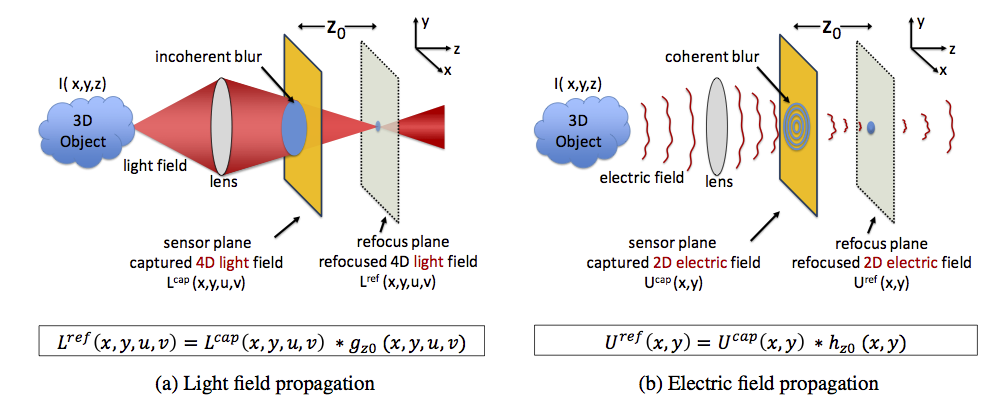
Figure 1:
Light field propagation vs. electric field propagation:
(a) Incoherent light
propagation through free space is represented by 4D light fields (in
some literature, propagation is expressed as a shearing of the 4D
light field, which can be represented as a 4D convolution). Light
field cameras capture 4D light fields on 2D sensors, resulting in
loss of spatial resolution. (b) Coherent light wave propagation is
represented by 2D electric fields. The 2D field can be propagated
between parallel planes by a 2D convolution. The coherent blur
encodes depth information and has broadband frequency response. This
enables digital refocusing without loss of spatial resolution.
|
');
$p->addSection('Project Description', '
Light field cameras allow us to digitally refocus a photograph after
the time of capture. However, capturing a light field results in a
significant loss in spatial resolution. In this paper, we propose
incoherent holography for digital refocusing without loss of spatial
resolution. The main idea is to capture 2D coherent holograms of the
scene instead of the 4D light fields. The key properties of coherent
light propagation are that the coherent spread function (hologram of a single
point source) encodes scene depths and has a broadband spatial frequency
response. These properties enable digital refocusing with 2D
coherent holograms, which can be captured on sensors without loss of
spatial resolution. Incoherent holography does not require
illuminating the scene with high power coherent laser, making it
possible to acquire holograms even for passively illuminated scenes.
We provide an in-depth performance comparison between light field
and incoherent holographic cameras in terms of the
signal-to-noise-ratio (SNR). We show that given the same sensing
resources, an incoherent holography camera outperforms light field
cameras in most real world settings. We demonstrate a prototype
incoherent holography camera capable of performing digital refocusing from only 3 acquired images.
We show results on a variety of scenes that
verify the accuracy of our theoretical analysis.
');
//$p->printSections();
// Add publications here. You can use either the publication number, or the full title //$p->addPublication(321); //$p->printPublications();
$p->addSection('Publications', '
"Digital Refocusing with Incoherent Holography,"
O. Cossairt, N. Matsuda, M. Gupta,
IEEE International Conference on Computational Photography, 2014.
[PDF]
' );
$p->printSections();
// Add images here. Args are (url to image, url to thumbnail, title, description)
$p->addImage("images/Simulations.png",
"images/Simulations_thumb.png", "Digital Refocusing with a Coherent Spread Functions (CSF)",
"Here we provide a simple simulation demonstrating how refocusing a hologram is carried out simply as a convolution with a 2D CSF.
The scene consists of three playing cards
placed at different depths. The coherent spread functions (CSF) for
the cards vary in size according to their depths. The CSFs have the
shape of a sinusoidal zone plate. Consequently, high spatial
frequencies are preserved in the hologram even though the maximum blur diameter is nearly half the image width.
In contrast, the incoherent PSFs in conventional imaging act as low-pass filters.");
$p->addImage("images/prototypeCamera.png",
"images/prototypeCamera_thumb.png", "Prototype Incoherent Holography Camera",
"Our prototype camera utilizes a Michelson interferometer setup.
A cube beam splitter divides incoming light from the scene into two beams.
Two mirrors then reflect the beams back towards an objective lens
that images the wavefront onto the sensor.
One of the mirrors has a small amount of curvature to shift the focus of the beam
relative to the other path. A piezo-actuated mirror creates sub-micron
displacements that are used for phase shifting.
The mirrors were both 25.4mm diameter and the objective lens was an
50mm focal length lens (Edmunds Optics 59-873),
resulting in an aperture setting of approximately F/2.
For the sensor, we used a 1/2\" monochrome
10 Mpix sensor with 1.67um pixels (Edmunds Optics 86-749).
For the color filter, we used a 10nm bandwidth interference filter
with center frequency 632.8nm (Thorlabs FL632.8-10).");
$p->addImage("images/Geometry.png",
"images/Geometry_thumb.png", "Incoherent Holography Geometry",
"The figure shows the geometric parameters of an incoherent holographic camera. A Michelson
interferometer setup is unfolded and the two paths are shown independently. The key property
is that each point source is divided into two point sources with slightly different radii
of curvature. The two point sources are then recombined and interfere on the sensor plane,
reproducing a Point Spread Function (PSF) very similar to the optical propagator for a coherent optical field (i.e. the CSF).");
$p->addImage("images/PSFDecompose2.png",
"images/PSFDecompose2_thumb.png", "Incoherent Holography Capture Decomposition",
"The incoherent holography PSF consists of a sum of four different PSFs.
As a result, the captured image is a sum of four different blurred images. Two of the images
are simply blurred by the incoherent PSF from the two point sources in the
Michelson interferometry setup. The other two images are blurred by the CSF. Phase shifting is used
to remove the undesired blurred images.");
$p->addImage("images/NoiseSimulations.png",
"images/NoiseSimulations_thumb.png", "Noisy Simulations for Digital Refocusing with Incoherent Holography",
"We show that The MTF of an incoherent holography system is inversely proportional to the maximum blur size.
In this simulation, the scene consists of three playing cards placed at
different depths. Gaussian noise is added to captured images with a std-deviation of &sigma=.005.
The camera is focused on the front card (Depth 1).
The scene depths are chosen so that the maximum blur size is 32
pixels (top row) and 64 pixels (bottom row). (a) The three input
phase-shifted images. (b) The recovered holograms. The front card is
in focus, and the other two cards are blurred. (c, d) Images
refocused on the middle card (Depth 2) and the back card (Depth 3),
respectively. Image noise is higher for the larger blur (bottom
row).");
$p->addImage("images/NoisePlot.png",
"images/NoisePlot_thumb.png", "RMSE for Digital Refocusing with Incoherent Holography",
"We derive analytic expressions showing that The MTF of an incoherent holography system is inversely proportional to the maximum blur size.
Since the MTF of is flat over the
passband, this means that SNR falls off exactly in the same way, producing significantly greater
SNR than a full resolution light field camera.
To verify this result, we perform simulations with a variety of blur sizes and
add Gaussian noise with &sigma=.005.
As shown in this plot, the increase in noise
is linear, where it is evident that the ratio of RMSE
deblurring error is approximately equal to the ratio of blur sizes.");
$p->addImage("images/Results1.png",
"images/Results1_thumb.png", "Experimental results for
digital refocusing",
"A Playing cards scene. Depth range is approximately 75cm and the maximum
blur size is approximately 1200 pixels.
The scene was captured at full 10 Mpix resolution. The exposure time was 1/3 sec
due to the amount of light blocked by the interference filter. The small pixels have a
very small dynamic range, and we averaged 100 frames and used denoising software to increase the SNR to a reasonable level.
The right image shows the coherent field recovered after phase shifting, which is focused on the King in
the background. The center image shows the results after refocusing on the Jack in the foreground.
The Jack is seen to come into crisp focus while the King becomes significantly blurred.");
$p->addImage("images/Results2.png",
"images/Results2_thumb.png", "Experimental results for
digital refocusing",
"A Diner scene. The depth range is approximately 50cm and the
maximum blur size is approximately 600 pixels. The right image shows
the coherent field recovered after phase shifting, which is focused on
the diner in the background, while the fence is severely blurred. The high frequencies in the fence
are still visible even with an extremely large blur size. The center
image shows the the fence come into
focus while the diner becomes blurred. ");
$p->printMedia("Image", $p->images, $p->imgnote);
$p->sections = array();
$p->addSection('Acknowledgements', 'Oliver Cossairt and Nathan Matsuda acknowledge support through
a Samsung GRO grant.');
$p->printSections();
$p->sections = array();
$p->addSlides("Refocusing Videos for Experimental Scenes", "presentations/SupplementaryMaterial.pptx");
$p->printSlides();
$p->sections = array();
//Add related projects here. The only argument is the relative path to the project (something like "../scene_collage/")
$p->addRelated("http://www.cs.columbia.edu/CAVE/projects/limits/", 'When Does Computational Imaging Improve Performance?');
$p->addRelated("http://www.cs.columbia.edu/CAVE/projects/flexible_dof/", 'Flexible Depth of Field');
$p->addRelated("http://www.cs.columbia.edu/CAVE/projects/shape_focus/", 'Shape From Focus');
$p->addRelated("http://www.cs.columbia.edu/CAVE/projects/focal_sweep_camera/", 'Focal Sweep Camera (Fosera)');
$p->printLinks("Related Project", $p->related);
$p->printSections();
$p->printFooter(); ?>